As a component of our ongoing continuous development program we have made a number of small alterations over the years to improve the utility of the reverse rollers that are used to engage the blade roots during a reverse action.
- Increased the diameter of the reverse screws that hold the rollers from UNC 1/4" to M8
- Increased the height of the rollers to increase the area in contact with the blade roots
- Added a cap to the upper section of the rollers to prevent antifouling binding the roller
- Replaced the V10 conical reverse rollers with a conical / triangular design that both rotates and slides
- Increased the height of the V10 rollers by 2.0 mm to accept the same polythene cap as the Tri Rollers
Some Saildrives - namely Yanmar SD20's have dog type clutches with instant engagement that generates very high forces on the blade roots during reverse action. Higher powered engines and those with higher reverse speeds as well as the corollary of larger blade sizes - now 19.50" on the K3 increasing to 20.50" on the K4 - have all further increased the forces on the blade roots during reverse.
In addition we have found particulary in coral seas where there is a very level of carbonate in the water which invariably deposits on the propeller components, that this tends to freeze the reverse rollers so preventing them adopting a rolling action when engaged against the blade root during reverse. All these variables tend to produce higher wear rates on the blade roots than is desirable over time.
As a result of extensive testing with a number of different roller designs ranging from 5 sided to 4 sided and eventually 3 sided rollers we have committed to what we term a Tri Roller design which consists of a larger taller roller to capture the functionality requirements listed above - but also convert the rolling motion into initially a rolling motion and then transitioning to a sliding motion.
The three flat sections milled off the roller are then faired to the original conical section so that as the flat sections slide across the blade root while still under a torque tending to " dig in " the leading edge, the faired section acts like the nose of a bob sled riding smoothly over the softer composite blade material.
Because the Tri Rollers are forced to rotate by the changing angle of contact with the blade root as reverse is engaged, and protected from deposits by the cap - they remain free to move despite high levels of fouling from carbonate and other deposits over time.
We now have many months of service from over 200 installations and can report blade root wear has been reduced to barely discernable levels even on high use installations such as whale watching catamarans.
From March 1st 2015 - these will be fitted to all future units as standard with the polyurethane caps to prevent antifouling and deposits freezing the Tri Rollers on their M8 mounting screws.
The small hole in the center of the caps allows for greasing with the standard Kiwiprops grease nipple supplied but care must be taken as excess pressure will simply force the cap off. If this occurs then the cap can be tapped back into position by slight tapping around the perimeter of the cap which allows excess grease to come out and reduce the pressure constraining the cap from being remounted.
Greasing is essential initially and will be loaded during assembly but not essential subsequently if not being antifouled. Certainly additional greasing is useful as the presence of any grease will certainly assist in ensuring a minimum of deposits and fouling on the bearing surfaces over time.
The cap also prevents antifouling binding the rollers to the mounting screw - a frequent occurruence that prevents the rollers turning and again exacerbates wear on the blade roots. These must be free to turn post antifouling.
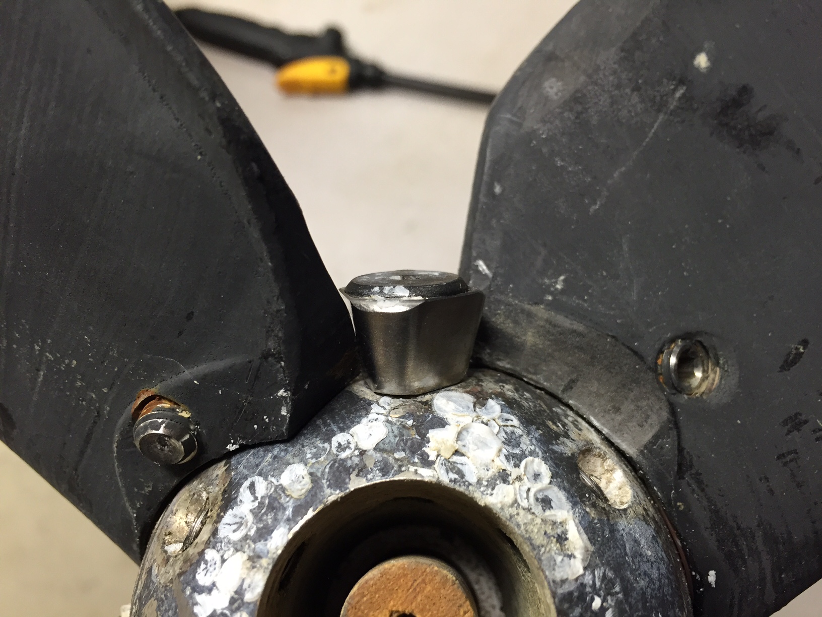
The photo below shows the Tri Rollers installed on a unit that motored from NY to Florida via the ICW and return. Note the near zero wear patterns on the blade roots. This was a 3YM30 on 2.61:1 shaft installation. The shiny surface of the Tri Roller indicates that the Tri Roller is rotating as designed and keeping the surface of the roller clean.
Update as at June 2015 ...
As part of our never ending quest to improve the performance and utility of the units and minimise all wear patterns, we have observed that in a very few marginal situations we can reduce blade root wear patterns to zero by the addition of a matching SS wear pad on the blades that accepts the Tri roller contact area when the reverse functon is engaged.
We have spent many hours testing various additions and possible modifications while targeting ease of installation, economics and utility. Stand tests that can emulate, but never replace, in service tests indicate with very high levels of confidence that the addition of what we term an impact screw into the blade root at a jig bored position on the blade wear pad will benefit those very small number of installations in delivering zero blade root wear over long time frames.
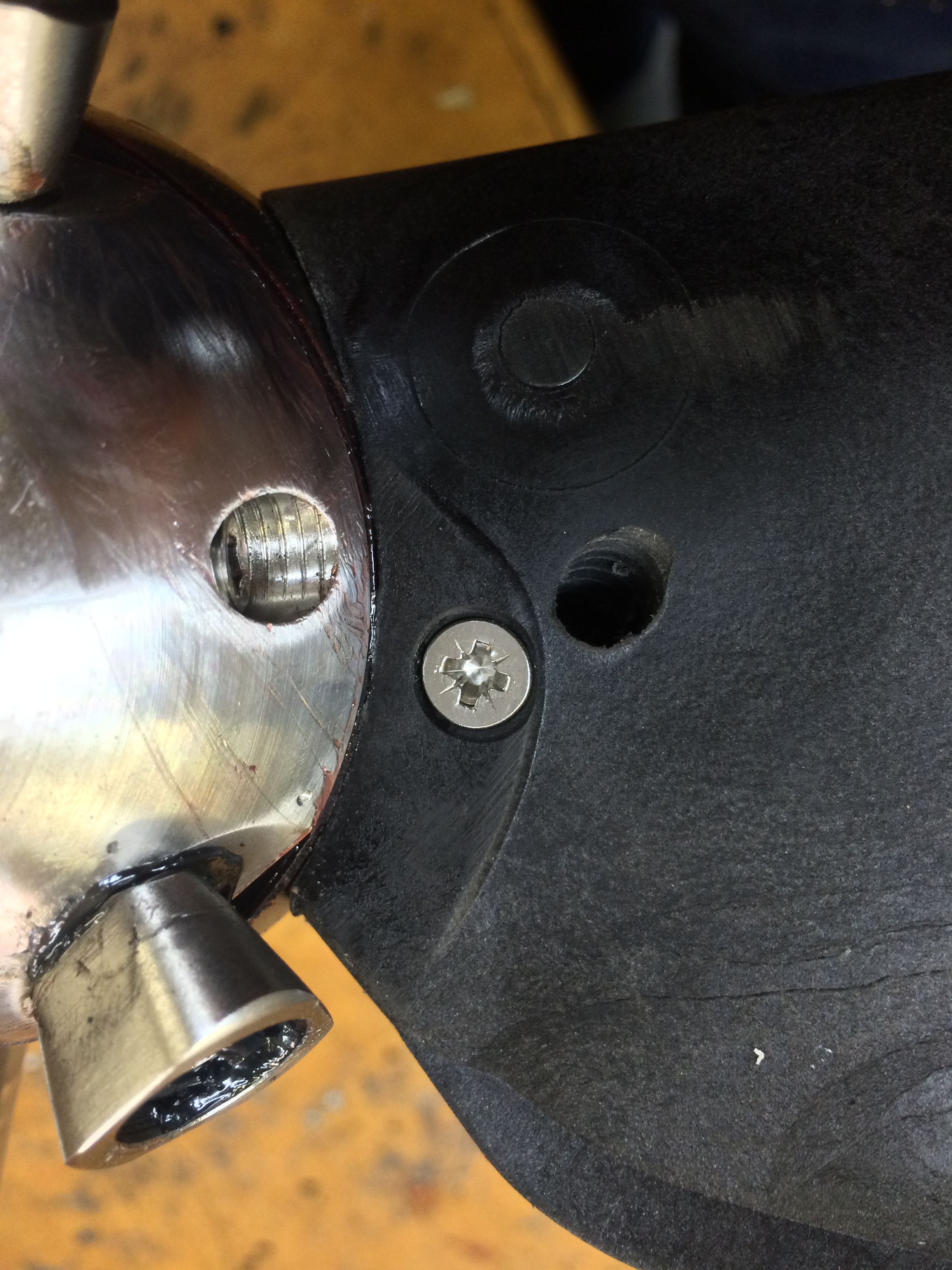
The photo below shows the addition of a jig located and bored self tapping Stainless 316 8g Pozidrive 13 mm screw positoned to accept the Tri Roller impact at the point of maximum force. This is also where the roller reverses it's sliding motion as the reverse function completes the engagement motion. This coincides with the point of maximum wear and it makes sense to target this point rather than the whole pad area on the blade root which shows no wear over long time frames on high time installations.
We needed to consider economics, method of attachment, mass and particularly corrosion potential over time - and are confident that this version modification will be successful over long time frames in service on both K3 & K4 units where it is installed when we think appropriate.
The photo below for a left handed blade shows the SS 316 8g x 13 screw inserted in a K3 unit. This modification applies to both K3 & K4 units that share common blade designs. Note also the faired rollers to the left.
FEBRUARY 2016:
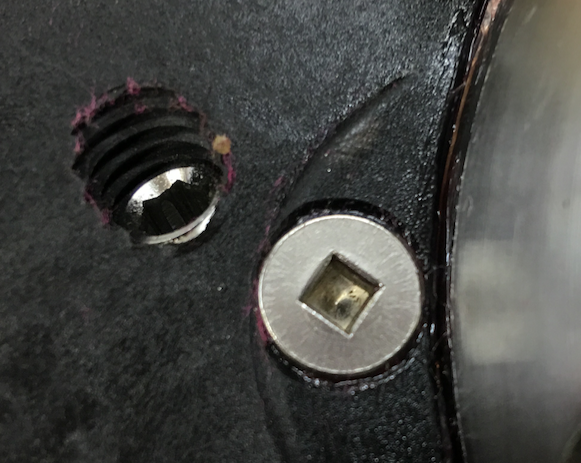
With the availability of heavier # 10 gauge square drive screws in SS 316 - we switched to these having more metal area to contact the Tri Roller. The increased Ø does not interfere with the pitch screw which is very close at the center of the blade. It is not intended that these would ever need to be removed so are installed with 272 Loctite™. The larger surface area and reduced central recess all contribute to lower force / unit area and lower wear rates over time.
OCTOBER 2016:
Below is a photo of a K3 unit one year after installation on a new cat with 40 hp Yanmars and SD60 Saildrives. The vessel was used extensively through the season but is showing virtually no wear on the blade root as at the October 2016 haul out.
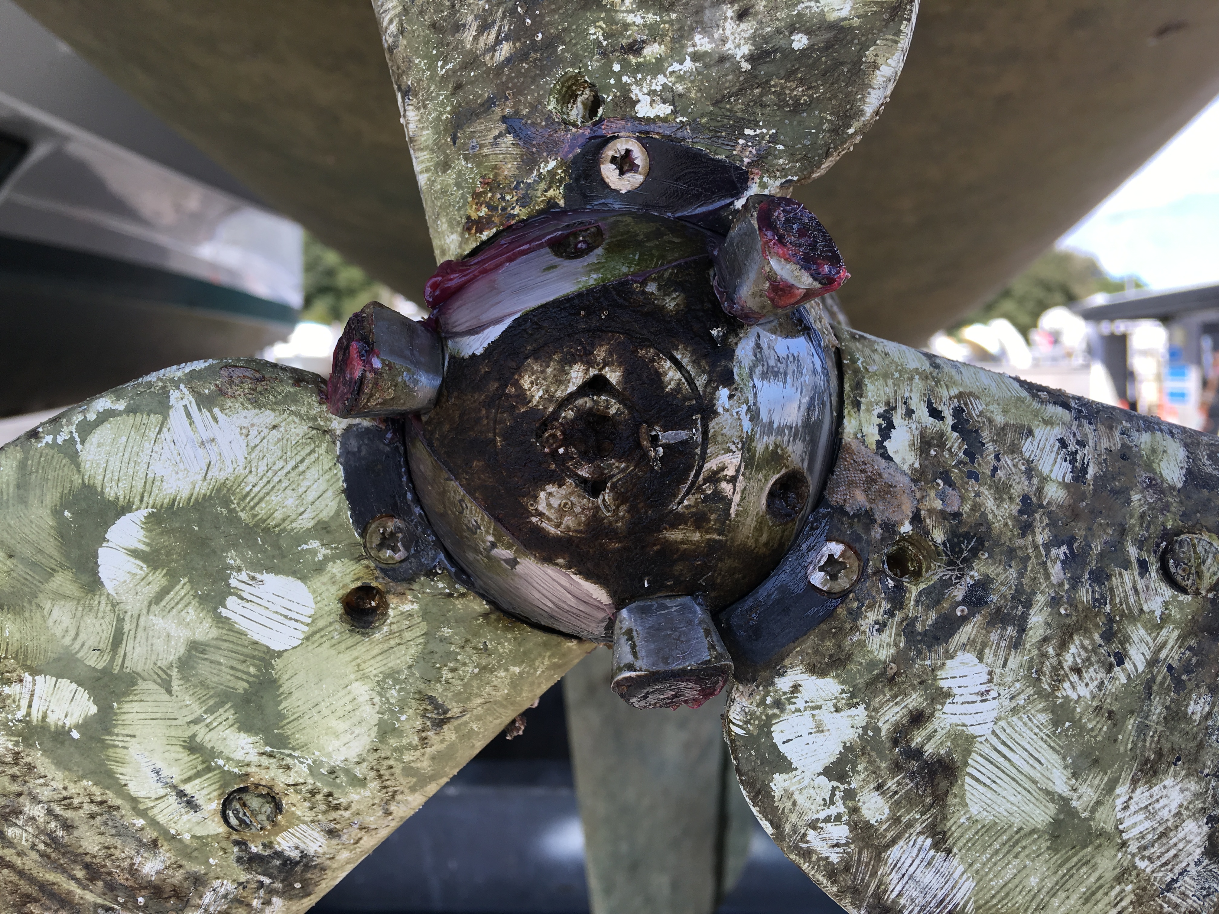
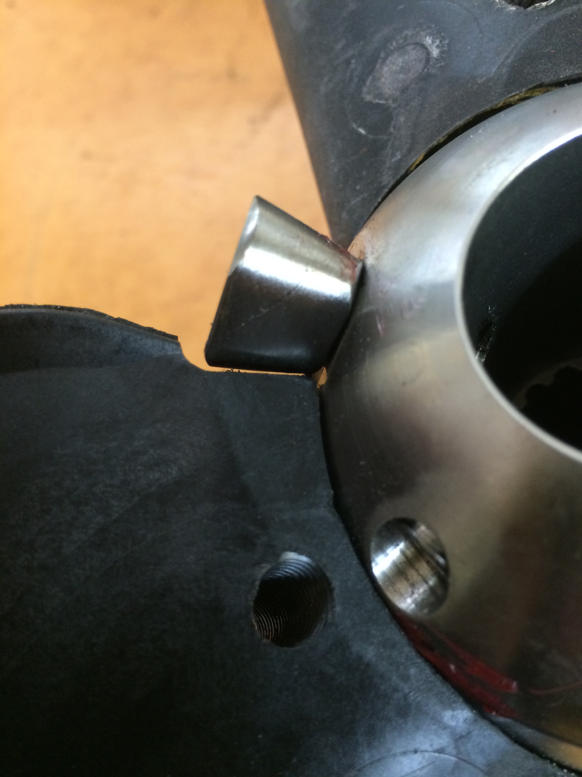
This close up photo shows the material removed from the trailig edge of the blade to allow the blade to pass the Tri Roller which has a larger diamter than the previous conical roller.
RETROFITTING TRI ROLLERS TO EXISTING BLADES:
The photo below show the trim pattern required to ensure the blades pass the Tri Roller with larger conical section. This can be done with a coarse square file or similar.
In any refubishment scenario we would recommend upgrading to these new components which have now been installed on over 1000 units and demonstrated their ongoing utility and durability in service.