Blade Mounting K3 & K4 Units
DO NOT REMOVE THE BLADES SIMPLY TO GREASE THEM ....
NB: Current models use neoprene V seals - not O rings. The recess in the blade roots for these two seal types are different.
NB: If ever removing the blades - you have to re-use the same blade mounting pins, ensure they are turned 180º to expose a new wear surface to contact with the outer edge of the groove in the blade carrier casting. This will reduce the tolerance for the blade to move out the blade mounting pin and thus ensure that the V seal in the blade root is correctly pressured against the casting for maximum grease retention capabilty.
NB: New or replacement blades are always provided with mounting pins which in current build versions will be to the threaded & capped design in use since early 2014.
IF BLADES WITH ORIGINAL BUILD PRESSED TYPE PINS ARE REMOVED - IT IS STRONGLY RECOMMENDED THAT THEY ARE REPLACED WITH CURRENT BUILD THREADED & CAPPED TITANIUM BLADE PINS WHICH WILL REQUIRE COUNTERSINKING BOTH BLADE FACES TO GENERATE A REDUCED HOLE LENGTH OF 25 mm.
THIS REMOVES ANY POSSIBILITY OF THE HOLES BECOMING DISTORTED OR WORN AND PINS BECOMING LOOSE.
UPDATE as at Jan 2014: THREADED TITANIUM PINS:
As a result of feedback over time and extensive testing and review we are now in the process of incrementally offering a new versionÂÂÂ of the Ti pins that hold the blades on. This will ensure the blades cannot come loose under any circumstances irrespective of how many times they are removed. The body of the pins remain with an Ø = 6.35 or 1/4". Subject to satisfactory results from customers over time we plan to install these as standard on all units.
One end will have an expanded head of 8.00 that will prevent the pin ever coming out one way, and the new head will be used to drive the pin into the blade in a press fit in exactly the same manner as at present that has not changed since 1995. This uses an undersize hole to retain the pin using the plastic qualities of the blade material.
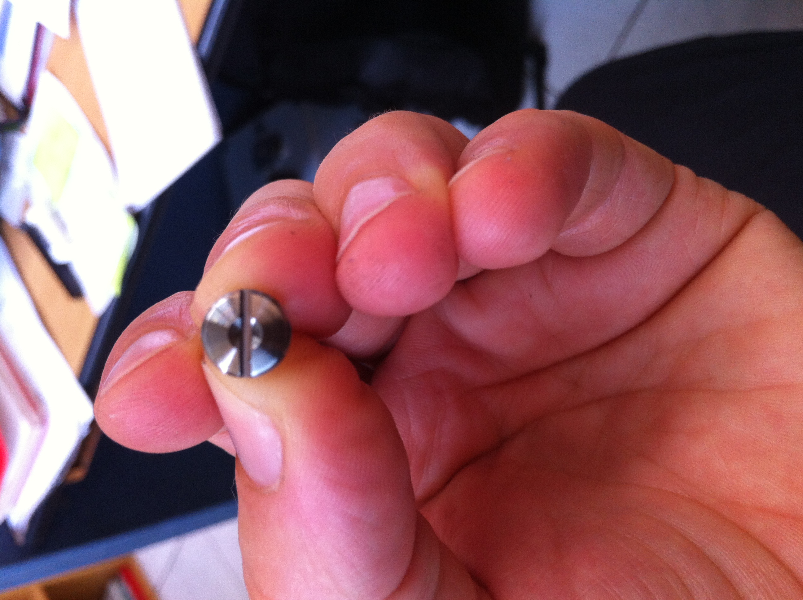
This pin however will be tapped M5 internally at the other end. A short threaded M5 cap screw will then be mounted and screwed home with a flat screw driver inserted into the 1.50 wide slot across this head. Thus the threaded end can be easily identified even after antifouling has been applied as only it is slotted. Subsequent batches will have a recess in the slot to differentiate the cap end which can be turned vs the pin headed end which can not - but will be slotted to allow for holding a pin that has become less tight to allow the cap to be unscrewed.
Use an electric drill on IMPACT setting to easily remove a cap when the pin is rotating.
DO NOT USE RED ie HIGH STRENGTH Loctite™ on the threads. With the area in contact with the threads and the underside of the cap in contact with the blade surface you will need to drill the cap to remove the pins - so they cannot be then be reused.
WE RECOMMEND BLUE or MEDIUM STRENGTH Loctite™which provides very adequate locking but still allows for the cap to be unscrewed subsequently if ever required. The cap end will be marked with a small recess in the center of the slot - it is this end that must be unscrewed.
There is no normal need to remove the blade mounting pins as the blades are greased without removal. If the cap is drilled off you will of course need a new set of pins to replace the now damaged pin minus its head and with the remains of the cap screw in the end of the pin.
Simply tightening the cap into the pin and the addition of any antifouling should be more than adequate to keep the cap screw permanently in the end of the pin in the absence of medium strength Loctite™ which we do recommend.
Removal of the pin, if ever required, requires that first the slotted cap screw must be unscrewed. Then and only then by using a hardened 3.00 Ø drift or pin punch the pin can be removed by hitting the base of the hole in the pin so as to avoid damaging the thread on the pin. This will need to be 30 long to tap the pin clear of the blade.
NB: Use an electric drill on impact setting to ensure ease of removal of the threaded cap. First provide a sharp tap to the opposite head end of the pin which will move / shock the pin through the blade and break the Loctite seal under the cap that is to be unthreaded.
To ensure the heads of the pins are near flush with the surface of the blade, they expect that the pin hole will have a standard counter sink of 45º on each side, bored parallel to the hole not the surface, that generates an Ø = 8 - 9 mm on the blade surface(s). If the C/Sinks are not present or of a smaller dimension they should be expanded using a normal woodworking or metal C/S that is 90º between the faces thus cutting a 45º face on each side. This then allows the new pin the correct depth each side of the blade.
When these threaded pins are used they update and are in addition to the information provided below.
This photo shows the c/sunk on the end of the cap - to identify the cap end when both ends are slotted.
To ensure easy access if ever required to be undone - possibly underwater in extreme situations - we recommend inserting the pin into the blade so that cap below is on the aft side of the blade. This ensures the cap can be easily accessed from aft with a screwdriver.
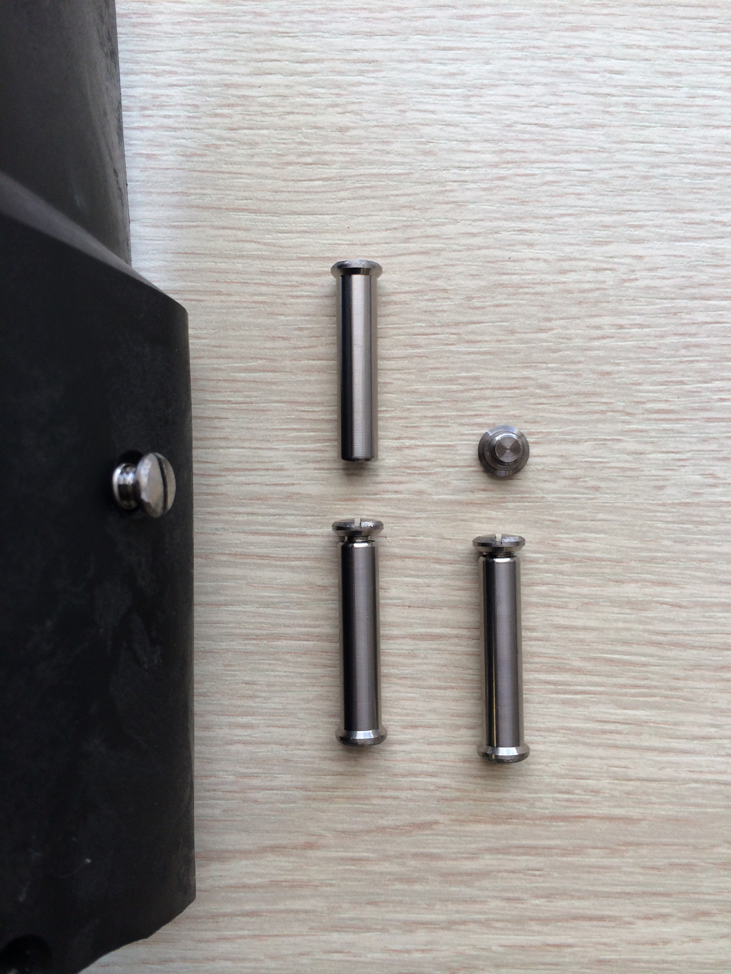
NB: V Seals superceded O Rings ~ 2008 and thus have a different recess in the blade root.ÂÂÂ They are not interchangeable but the same comments below apply:
BLADE MOUNTING:
The following steps address how to mount the blades on a Blade Carrier Assembly if replacing blades or if the unit has been delivered with the blades free - usually only in Dealer situations.
Check that the white V Seal is present in the recessed blade root. Note that earlier O rings are not compatible with the V Seal recess.
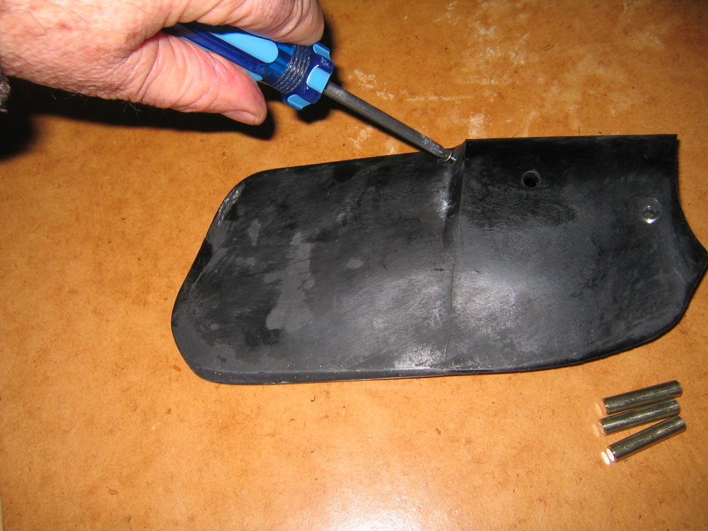
Remove the small pozidrive screw half way out each blade that is used to seal the grease recess once the blade is mounted. This will allow surplus grease to exit as the blade is mounted over the pin.
Place a smear of grease over the groove in the Blade Carrier to ensure it is full of grease post assembly and also place ~ 20 mm of grease down the mounting hole in the blade with a spatula or knife.
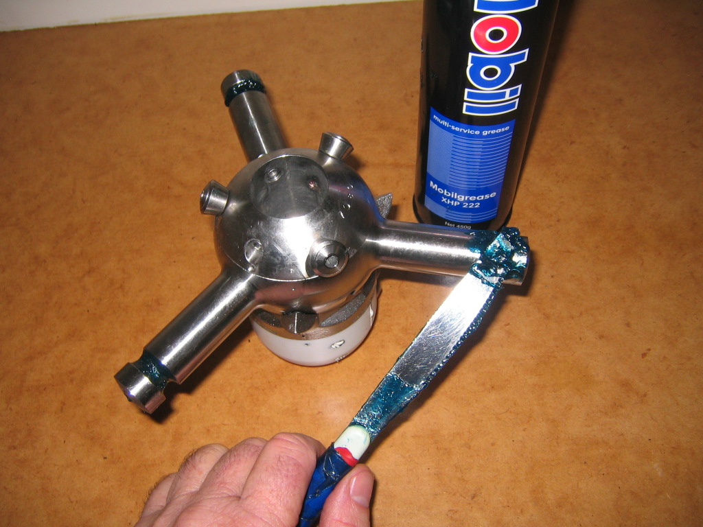
Insert about 20 ml down the blade recess smearing around the internal surface.

Now place the blade over the mounting pin in the arc that allows the blade to move freely between the pitch stop at one side and the reverse roller on the other. Force the blade down which will cause excess grease to ooze from the grease mounting hole.
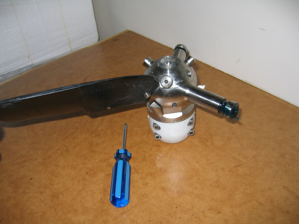
Place the Titanium pin with the head such that the threaded end will face aft when it emerges from the other blade face. This will facilitate ease of replacement if ever required by providing easy access from aft.
If the pin is showing any wear pattern from previous contact with the blade carrier - turn the pin so that a new surface is towards the outer end of the blade which will ensure the blade moves back down to it's original position towards the blade carrier thus eliminating lateral tolerances on the blade introduced from any pin wear over time.
Ensure the stricking action of the hammer has a downward component towards the leading edge of the blade to lift the leading edge of the pin and ensure it enters the opposite side of the blade cleanly - note hammer above pin as shown below.
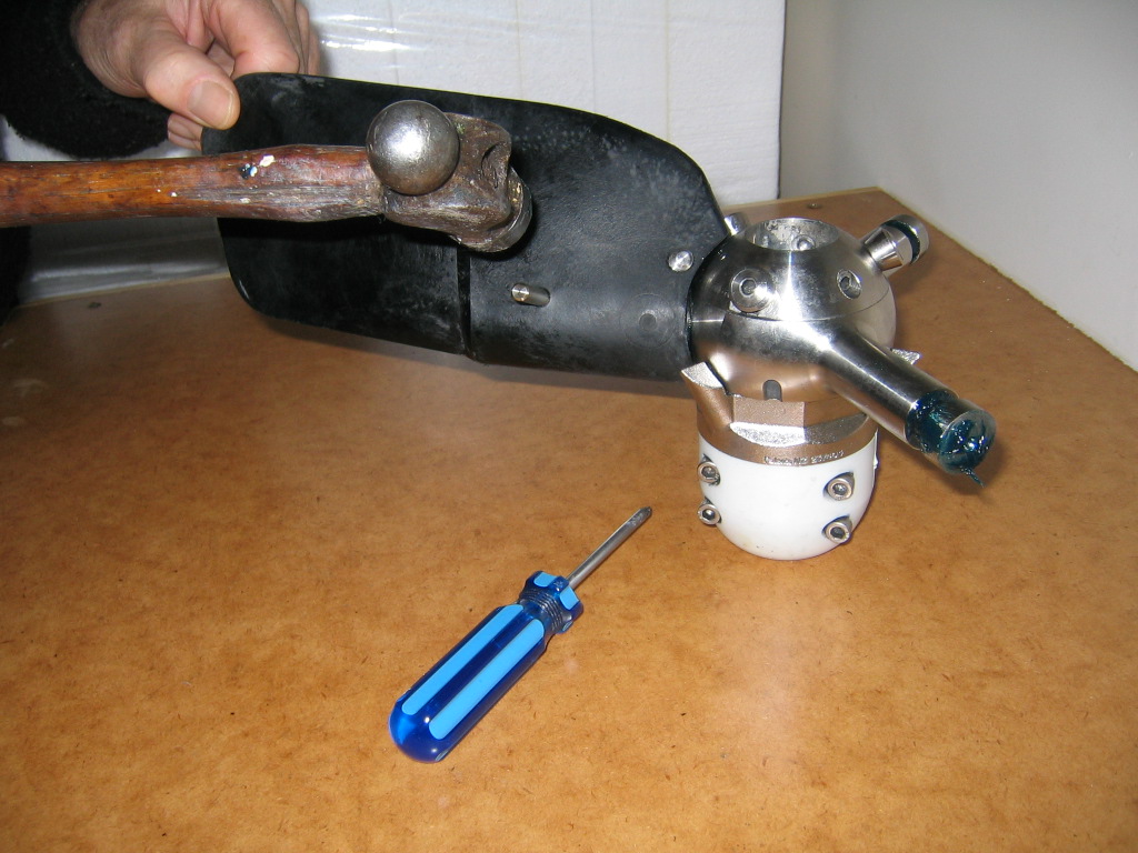
Remove any excess grease that has penetrated the female threaded end of the pin as it emerges. A toothpick or sharp object with a piece of rag will execute this very easily.
Now place a dab of Loctite™ or similar - Blue or Medium strength grade only - down the female threaded pin and insert and tighten the threaded male cap. Only tighten to a low torque level - the Loctite™ will ensure secure retention of the cap to the pin amd thus the security of the blade mounting over time.
After pushing the blade down to the boss to ensure there is room to insert the pozi grease retention screw without forcing the blade out under hydraulic forces - insert and screw home the pozidrive grease retention screws. Use very litle torque - they need only to pull down inot the recess - DO NOT OVERTIGHTEN.
Check that each blade in turn is moving freely through it's full arc of sweep as it will be in service.
If the blade is rubbing on the boss - place a strip of coarse emery paper or # 60 wet & dry on the boss to act as a spherical mandrel, then forcing the blade root down onto the emery - oscillate back and forth to sand down the blade root which increases the tolerances between the blade root and boss.

Repeat for each blade in turn.
The next step is to ensure the pitch is both set to the desired angleº AND the pitch is exactly the same on each blade. Use PITCH SETTING from the OPERATING MANUAL or the web site.