OVERVIEW:
Spring pre-tension performs a number of functions that need to be understood in setting spring tension:
A: The spring returns the Blade Carrier assembly on which the blades mount to the fully feathered position. This allows the blades to rotate from the motoring position with the pitch screw against the pitch stop - to traing aft and aligned with the axis of the unit - and then a further 25º past this trailing aft position. This allows the blades to adopt alignment with streamlines encountered from the various shaft angles derived from the shaft protruding from the hull. Saildrives wih shafts parallel to the waterline need only deal with much lower leeway and heel delivering streamlines relative to the unit less than the 25º design criteria.
B: If for what can be any one of many possible reasons - as simple as a surge off a wave - forces on the blades tend to rotate in the Ahead direction - then the spring tension must be sufficent with the gearbox in neutral that rather than allow the spring to wind up and in effect place the unit towards the Reverse position, the tension must be such that the shaft rotates in parallel with the blade assembly. This means no movement between the Blade Carrier assembly with the blades and the boss mounted on the shaft.
C: Obviously as spring tension increases it will become oprogressivly more difficult for the unit to engage reverse. In addition as spring tension is increased the internal dianeter of the torsion spring will reduce and can reduce such the the spring binds internally on the boss. This must be avoided as transferring the excess torque of the unit to the spring will damage the tails of the spring with forces well in excess of it's design.
D: While we preset the spring tension at delivery time to accommodate expected shaft torque ( Gearbox in neutral ) - it is important to ensure spring tension pre-setting accommodates the specific friction of the individual \vessel upon which the unit is mounted.
E: Spring tension must therefore be at the happy medium - siufficient to rotate the shaft in neutral - bt not excesive to prevent reverse engagement.
K4 units differ from the K3 units as the Nose Cone on K4 units is threaded and can be tightened by rotation to any position to remove the fore and aft tolernaces of the assembled components.
This means the Nose Cone cannot be used to accept the tail of the internal torsion spring as it's final position will only be determonei once tightened to eliminate the varying fore and aft tolerances of the components once assembled.
All K4 units contain thus have what we term a SS 316 collar aft of the Nose Cone and forward of the Blade Carrier assembly which accepts the forward tail of the internal SS 316 torsion spring.
This returns the unit to the feathered position post reversing to ensure the blades are free to fully feather.
This spring must be pre-tensioned to ensure that occurs. Right Handed propellers use a Left Hand wound spring. Left Handed propellers use a Right Hand wound spring - so are not interchangeable between Left & Right Handed units.
This collar is split on one side and is locked with an M8 Cap Screw closing the split and seizing the collar down onnto the shaft once the collar has been rotated to generate the correct spring tension.
In addition we have another M8 threaded hole opposite the split which serves two functions:
- By inserting an M8 Cap Screw into this threaded hole - it provides a very effective lever to move the collar to the correct position that will generate the dorrect spring tension. Once the M8 Cap has been tightened - it is then removed
- It provides for another M8 x 12 set / grub screw to be inserted and tightened down on to the boss to provide a second locking method of the collar onto the boss.
- To ensure easy movement of the collar - tap a slotted end screw driver into the join line ( which will be filled with mastic ) to spring the collar and then use this as a lever to assist rotation. Mastic from the join line in the Nose Cone can get into the surface btween the collar and nose during assembly and this may need to be broken to move the collar.
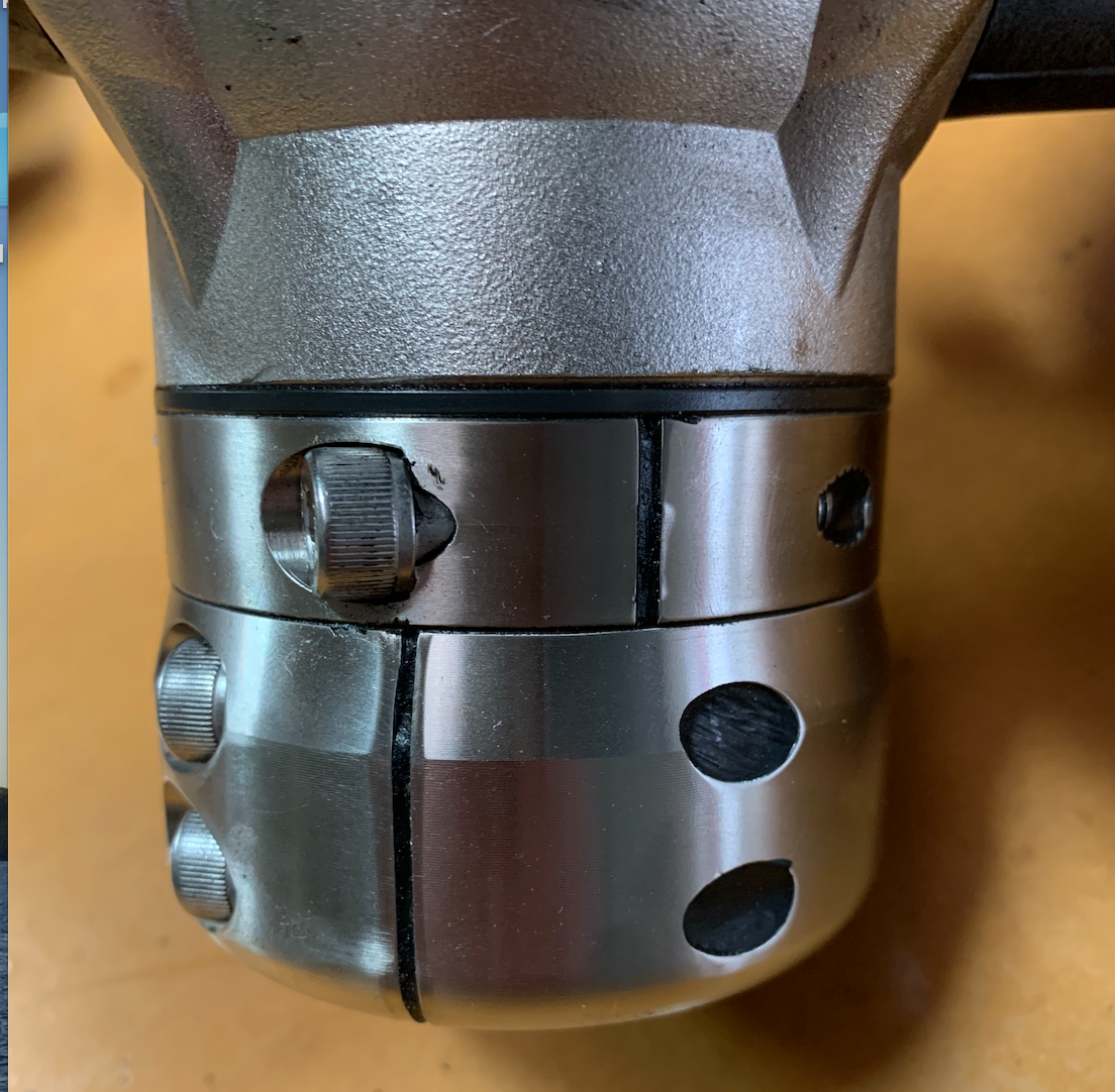
This photo below shows the M8 cap screw holding the split collar tight. The M8 grub screw is opposite.
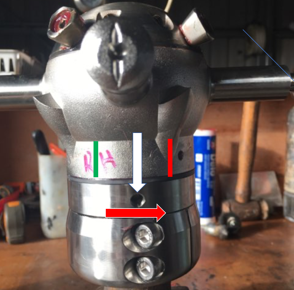
The photo's below for both Right and Left Handed units have a white arrow superimposed to show the M8 locking screw expected location relative to the Blade Carrier.
These position(s) will generate the correct spring tension to return the Blade Carrier assembly to the feathered posiiton.
In each case the M8 tapped hole in the collar shown should be moved in the direction that will rotate the Blade Carrier assembly to the feathered position. This will allow full movemet of the blades from the Ahead motoring position - past the centreline of the unit to a position of 25º over centre to accommodate shaft angles and leeway when sailing.
K4 - All Right Handed Units showing position of locking screw in targeted collar location:
Moving the collar in the direction of the red arrow will increase spring tension on this Right Handed unit.
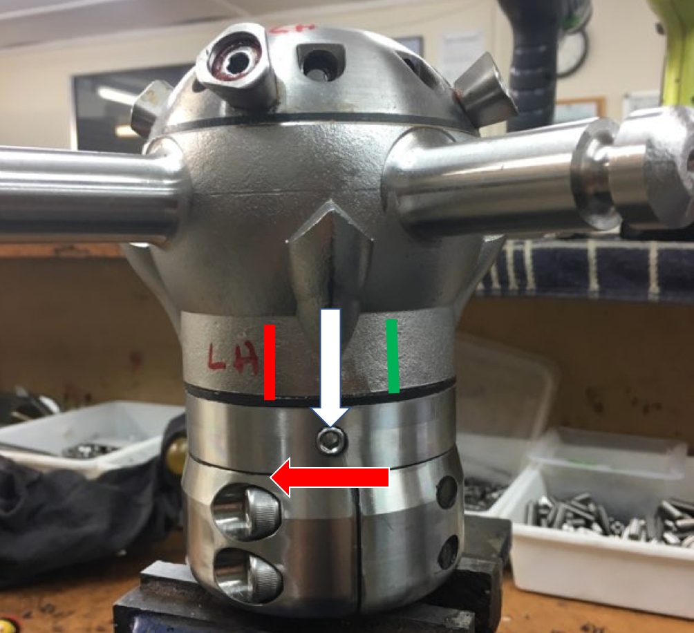
K4 - All Left Handed Units showing the position of locking screw in targeted collar location:
Moving the collar in the direction of the red arrow will increase spring tension on this Left Handed unit.
<br