Below is a summary of how to replace the Nose Cone - Shaft or Saildrive. The final step involves pre-tensioning the internal torsion spring. This may be needed to be undertaken independently if the Nose Cone has been moved - typically as the result of a rope wrap.
Steps are as follows:
Locate the alignment marks punched on the boss - see last page of K3 Operating Manual.
Mark relative position of all parts with indelible marker by drawing a line fore and aft
Find the matching mark on the old nose cone - if you have all parts
Undo all 4 cap screws completely
Lever off the half that holds the cap heads with a screw driver in the polyurethane joint line
Lever of the other half that tails the spring
Clean up the surfaces that the new cone will reside on including the groove recessed in the boss - using mineral turps or similar
Mark the new cone with the same alignment mark as the old.
Smear a very thin coat of polyurethane ( Sika or 3M ) over the nose cone with the spring tail hole semi circle that will contact the boss
Smear a very thin coat over the boss area now exposed. Make sure no excess will end up in the spring recess when set and cause binding.
Ensure a 45º ramp of mastic around the forward end of the thrust groove on the boss to ensure the nose will be forced aft to eliminate any fore and aft tolerances due to wear over time
Using a screwdriver to hold the spring out slip one half of the nose cone over the spring tail and tap in and down into position so the upstand in the nose cone clips into the thrust groove on the boss.
Smear about 3 mm on each half surface on the now fitted half nose and about 1 mm on the other half flat surface of the yet to be mounted half.
Fit the head half to the boss. Insert each of the 4 x cap screws threads in mastic which provides additional locking and tighten up to just start to pull the two halves of the nose cone together.
NB: You should expect a final gap of ~ 3 mm in the join between the two halves when completed - Do not expect the two halves to pull together and eliminate the gap in the join.
Tap the each half of the Nose Cone aft to eliminate any wear or excess tolerances in the assembly.
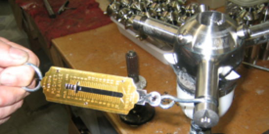
Insert the Allen Key into the Saildrive nose and use as a lever to rotate the entire nose to re-align the marks as before. Spring tension should then be as before and it should take ~ 1.5 kg or 3.5 lbs of force at the blade pin to start to tension the spring. For shaft nose cones insert the Allen Key into one of the cap screws and use as a lever to generate spring pre-tension. See last photo below.
Check the original alignment marks are now still in line as originally marked
Holding it there - tighten up the 4 x screws evenly to pull the halves together and squeeze out excess polyurethane. This must be done in stages to allow mastic to squeeze out. Simultaneously tap the nose cone aft to take out any excess wear tolerances in the assembly.
Nip up the 4 x screws - BUT DO NOT OVERTIGHTEN - it's tough - but still a composite. They must be tight enough for the nose to maintain it's position under the spring tension you have now loaded. Check again after 30 mins and tighten further if necessary. Final torque settings are 2 N.m for Saildrives and 2.5 N.m for Shaft drive style Nose Cones.
Tapping the blade carrier arms gently forward using a rubber hammer near the center can assist in adding tolerances / clearance to free up the assembly of it is binding.
Wipe off excess with a spatula then clean up with a mineral turpentine rag. Include the front face in the clean up to ensure clean contact with the Saildrive when finally mounted.
Allow the polyurethane to harden which can take some time. The next day is optimal or the polyurethane can be very messy.
Check the blade assembly will now rotate fully into the reverse position and return freely under spring tension to the sailing position where the blades are free to move fully through a fully feathered to engaged in an Ahead pitch position.
Grease the unit fully as per our web site video and your good to go.
The following photo's will show the correct position of the Nose Cones for both a Left and Right Handed K3 unit to enable a check as to the correct location of the Nose Cone joint line which will ensure the correct spring tension. Units are marked with pin punch marks post assembly - but these will not be there if a new nose cones is being fitted. If they can be transferred from an old nose cone - that would be of assistance.
Note that this join line on the Right Handed Shaft unit below is as shown relative to the heads of the Cap Screws. Ths opposite side will be in a different position.
Alternatively, assuming the unit was sitting on a flat surface nose up - then looking from the nose aft or down - you would initially rotate the nose, which holds the tail of the internal spring - so that it rotates the blade assembly that carries the blades into the motoring position.
In the motoring posiiton, the blades are free to rotate from touching the pitch stops as in motoring Ahead, to trailing aft as when Sailing, to ~ 25º past the due aft position to accommodate shaft angle.
RIGHT HANDED UNITS:
Right Handed units have Left Handed springs that would screw in if rotated in a Left Handed or Anti-clockwise direction. Left Handed units therefore have Right Handed Springs.
So for a Right Handed unit ( with Left Handed spring ) - looking down onto the nose - you would initially rotate the nose in a Right Handed or Clockwise direction ( Viewed from above - relative to the boss ) - so as to initially wind up the spring such that it moves the blade assembly into the Ahead position until it reaches the internal stops on the drive dogs on the boss.
You would then rotate the nose further - maybe ~ 8 -10 mm at the diameter of the pitch stop casting and nose cone join line to provide the pre-tension required to ensure the blade assembly will always return to the feathered position. The nose cone joint should then be aligned as shown in the photo's as follows. [ NB: Ths will vary slighty by unit as spring tension will vary by batch, heat treatment ]
RIGHT HANDED UNITS:
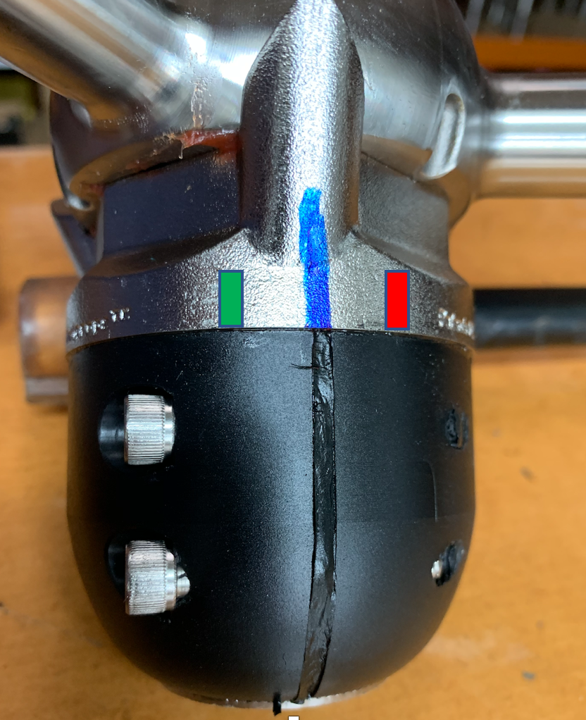
The photo below is of a RIGHT Handed Shaft unit - showing the joint line location of the Nose Cone relative to the Tripod casting such that the spring tension is correct for this spring. There may be slight variances between springs due to different material batches / tempering but the joint line will be very close to what is shown on this photo.
Note the position of the Cap Screws as the joint line on the other side will be in a different location relative to the Blade Carrier. This is because there are two joint lines but three tripod legs.
The joint line will indicate increased spring tension when nearer the red mark - less when nearer green.
LEFT HANDED UNITS:
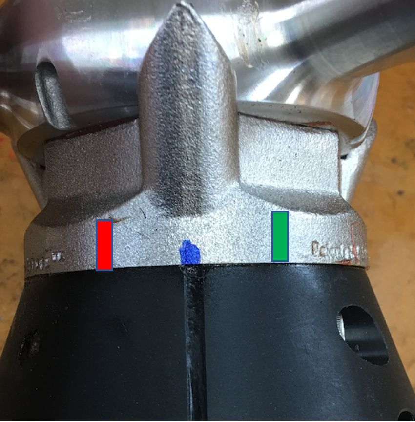
The photo below is of a LEFT Handed Saildrive unit - again showing the joint line location of the Nose Cone relative to the Tripod casting such that the spring tension is correct for this spring. There may be slight variances between springs due to different material batches / tempering but the joint line will be very close to what is shown on this photo.
Note the position of the Cap Screws as the joint line on the other side will be in a different location relative to the Blade Carrier. This is because there are two joint lines but three tripod legs.
The joint line will indicate increased spring tension when nearer the red mark - less when nearer green.
The photo below shows measuring spring tension to initiate movement of the Blade Carrier assembly from the Ahead or feathered position.