Ogival Foils
Ogival Foils - Developments, R & D, Planned Modifications, Test Results ... as at December 2015
NB: This web page remains under construction and will be updated as additional test data becomes available.
It has long been know that the optimal foil shape for a marine propeller is what is termed an ogival sectioned foil. This is flat on the back or aft face of the foil or blades and a section of a circle on the front face of the blades. More correctly - because the blade will have pitch and the unit will be rotating - the rear face of the foil will project a straight line at any given diameter. Imagine you bent a steel ruler to simulate a given diameter - then you could place the edge of the ruler onto the rear face of the propeller and it would co-incide with the rear face of the blade at the same diameter.
Of course this optimal motoring shape - which is asymmetric would be unstable in a feathering situation.
Kiwiprop blades have untill now used symmetric foils for three reasons:
A: A symmetric foil when feathered, and depending upon it's mounting, is stable in the streamlines it encounters and will feather much like a wind vane so aligning the individual blades into a minimum drag position when sailing
B: A symmetric foil only needs one set of dies which are always expensive to mould the blades
C: With the same shape each side of the foil - Left & Right Handed units can be manufactured from the same inventory which offers improved economics required to deliver the exceptional value package we are targetting to users.
With advent of open source software and the massive computing power now available on desktop machines at much lower costs than in the past - Computational Fluid Dynamics ( CFD) has become a realistic option to evaluate changes that could be made to Kiwiprop blade designs with the objective of improving motoring performance whilst retaining the feathering capability without the use of complex and very expensive gearing.
CFD will tell you in great detail the many characteristics of a particular foil - what it will not do is tell you what shape you should make that foil to deliver an optimal outcome. That is left to experiment and many countless hours of research on foil designs and their trade offs which remain one of applied maths most difficult of problems.
We began by using CFD and OpenFOAM - the open source software program - by investigating in a set of standard motoring and sailing conditions, the extent to which modfiying the aft face of the foil to a near ogival and then further modified near ogival section would alter motoring and sailing.
In all cases we were focused on the changes vs a standard existing foil rather than just an absolute outcome. We had good data from our own vessel so began with a similar diameter and pitch, the same rotation and shaft speeds and 7 knots sailing to build the first case for computation.
We then used the 3-D machine tool path of the original die for that blade shape and then formed the required mesh around that surface to allow for CFD to solve the many variables of pressure and torque around the foil.
Run times of a 27" iMac with 12 Gb of memory and a quad core 2.7 Ghz processor require about 2 hours to obtain 0.1 seconds of simulation along with absorbing 9Gb of disk space. Generating a 4 second video required additional computational power, all do-able using todays technology.
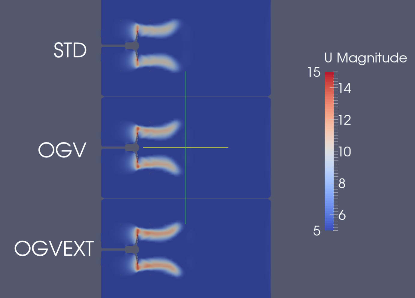
Below is the one of the first outputs showing the pressure as per the scale on the RHS of a section through the center of the propeller for both the standard foil at the top and the ogival modified foil below.
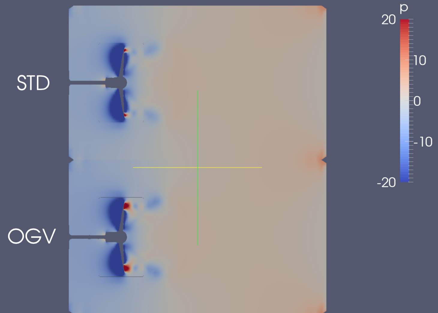
Clearly there is a much larger area of higher pressure on the ogival modified foil which from a motoring perspective is exactly the outcome we are seeking - ignoring for a moment the changes this will introduce to the feathering capability at this stage.
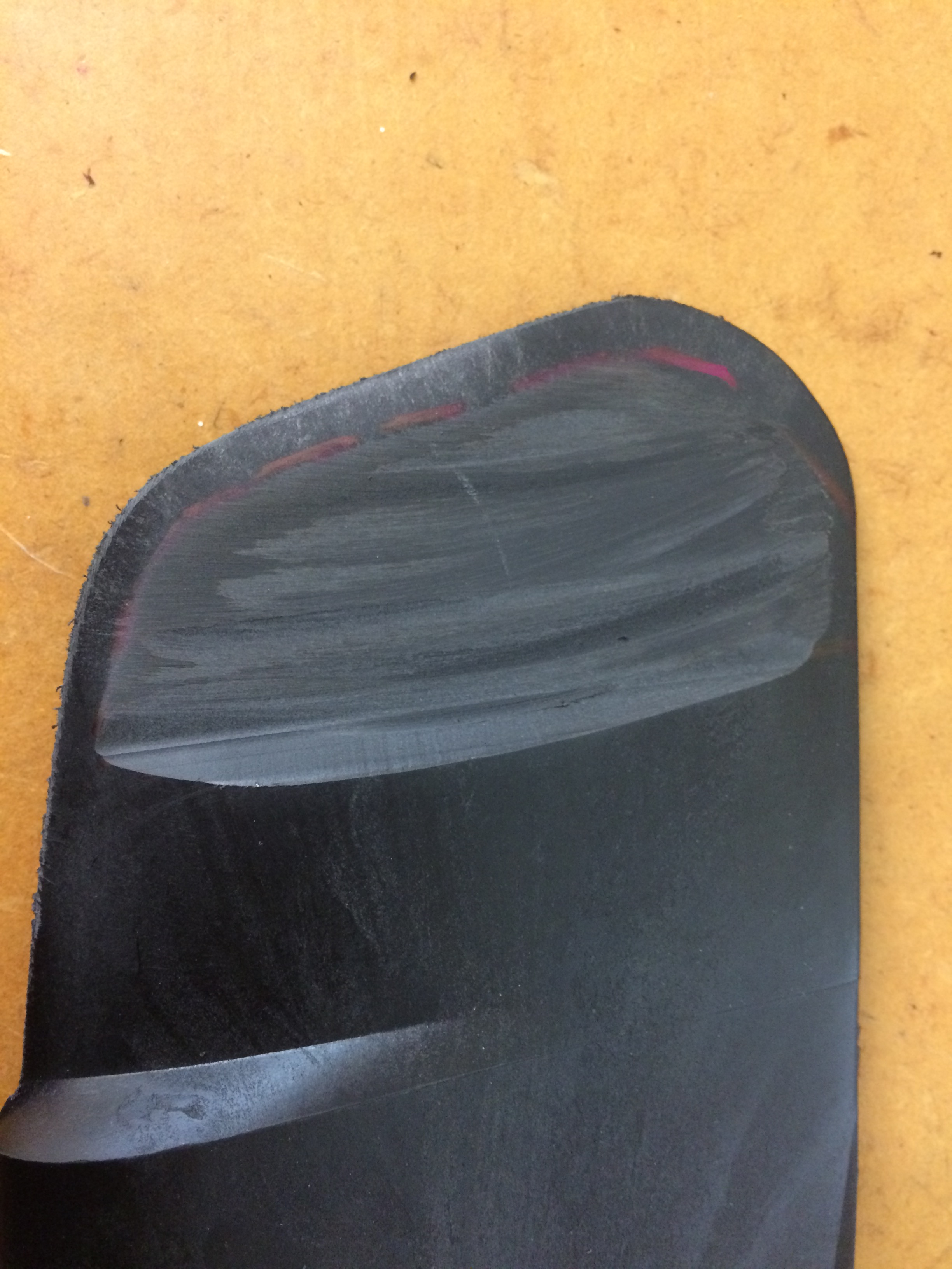
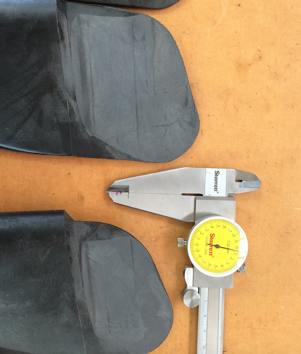
We then proceeded to mill a section off the rear face of a 16.50" blade to a depth of 50 mm from the tip and a height of 1.50 mm above the joint line of the die representing the center of the foil. We faired this along the run out line then tested this on our own vessel. The results were as predicted - an improved motoring capability whilst the feathering function was retained with reverse rotation when sailing of ~ 60 rpm and 1 ft-lb of torque.
This was very encouraging so we proceeded with further more aggressive modifications and installed tests all of which occupies a lot of time having to change the unit over and then wait for the range of conditions from calm for motoring for strong breezes to obtain sailing speeds up to a steady 9 knots - near maximum for a Townson 36'.
Below is a photo of the most aggessive ogival modification where the foil is flat down to the depth of the inflexion point, the depth of the face coincides with the join line, the foil is lengthened forward, the front face is fattened to a thicker foil, the foil is extended aft and an expanded V foil to provide bias for stability is seen at the lower left to counter these forces was added.
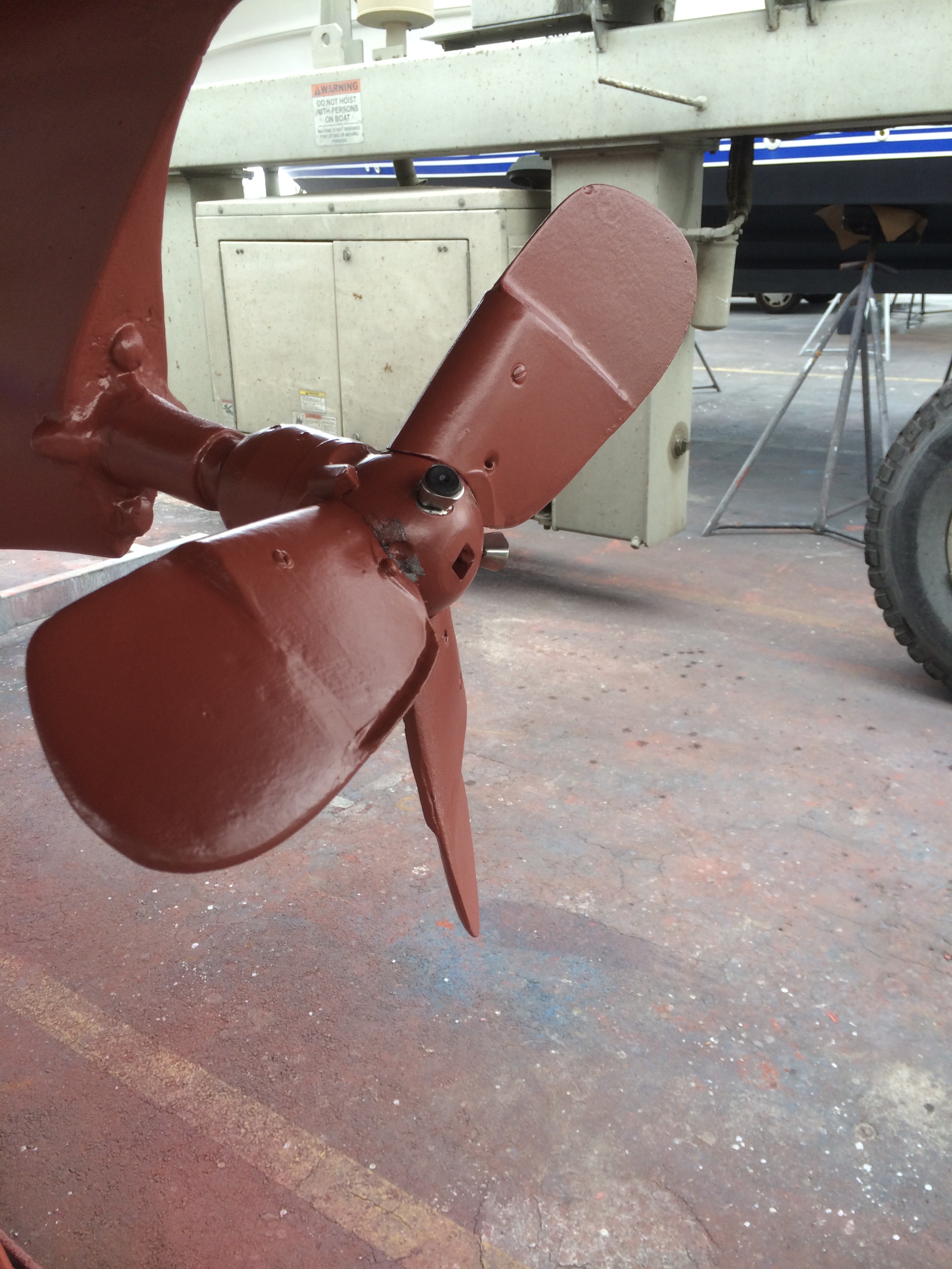
This configuration delivered superb motoring much as one would expect of a fixed 3 bladed unit and in fact overloaded the engine, but did not offer an adeqate margin of safety of the feathering function when sailing at high speed. This was exactly as predicted by the CFD program which gave further confidence in the OpenFOAM program and approach adopted. Note the addition of the larger V foil on the lower blade root forward face as shown on the left of the picture.
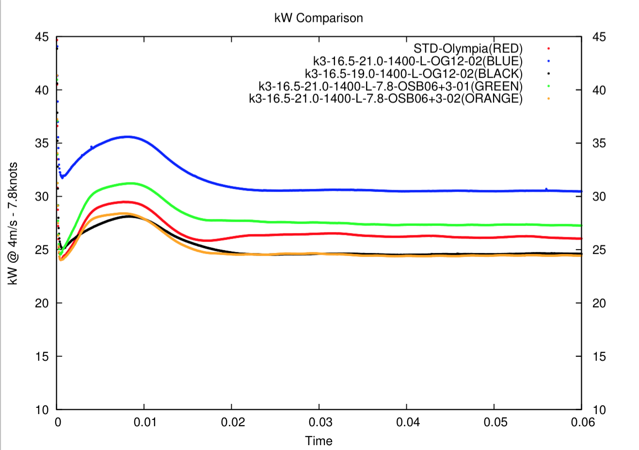
We than ran further calculations showing the power requirements for various cases illustrated below. The initial starting loads can be ignored - we need to look at subsequent stable operations to obtain relevant comparisions. Again these cases provided strong correlations with actual in use feedback.
The blue line case was the most aggressive ogival modification pictured above and consumes more power. This was at 21º of pitch. When the pitch was reduced to 19º as in the black line - all other variables held constant - the power requirement is reduced significantly, exactly as occurs in practise, again offering confirmation of the validity of the CFD approach. The other variables are for a 3 bladed 16.50" diameter unit, left turning @ 1400 rpm.
We then ran further cases only this time extending the ogival section much closer to the blade root to increase the area of ogival section. This case below shows the differences between a 50 mm ogival extension and a 100 mm extension. Clearly from just a motoring perspective it would appear initially this modification would be a plus. Of course a lot more calculation has to be done to check torque required and compare efficiencies. These diagrams show relative velocity at a center section of a 4 bladed unit.
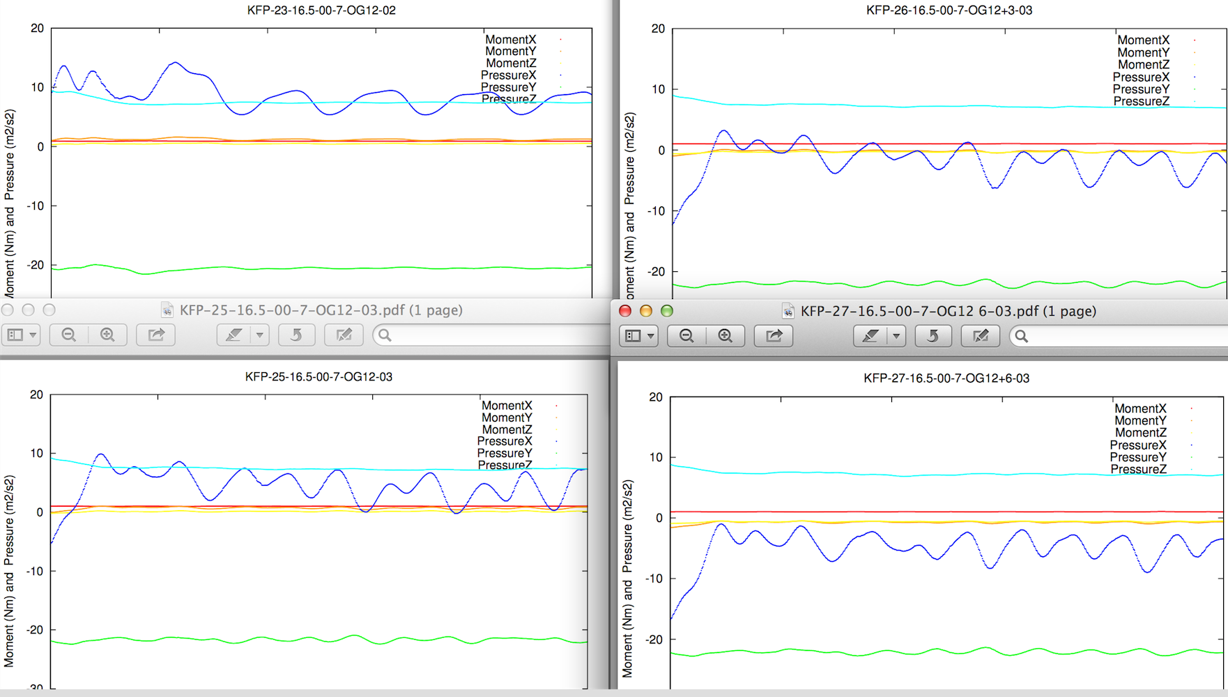
Now reverting back to feathering functionality - we needed to calculate moments about the blade's mounting pin on all 3 x-y-z axis for multiple cases with the flat face initially on the join line of the dies and then being raised up a distance - in each case reducing the ogival form for a more and more modified section with reduced motoring capability. These graphs show time along the x-axis and show the expected stability of the foil under the chosen scenario. In this case a 16.50" blade at 7 knots with 120 mm deep ogival section with two different V foils at the rear of the blade and a 3.00 and 6.00 lift off the center of the foil.
What it shows is the positive impact stability wise of the increased V foil addition to the rear of the blade and how increasing the distance from the foil center ie reducing the ogival effect both provide positive feathering inputs - but of course will both be negative to motoring utility.
Note how the moment about the Z axis ( Blue ) comes down and goes negative over time as the face is lifted 3 mm above the center of the foil and extends this as it is lifted 6 mm.
A blue line below the x-axis indicates the unit will tend to rotate in reverse with a very low torque when sailing which is what we want as an outcome. The unit can then be locked in gear to prevent wear on the blade mountings - yet will remain feathered even when fouled with the inevitable build ups on the blades over time and blade impacts with seaweeds and plastic flotsam during operation for example.
Having now established the superiority of a modified ogival foil and the extent to which that can be imposed on our blades while retaining both motoring and feathering functionality - we are now focused on implementation in terms of appearance and the removal of stress points by eliminating the discontinuity the initial approach has generated. Once a final shape is determined by the one-off milling of samples and trials on an actual sailing vessel - we can then use this for a die modification that will remove incremental labour inputs and deliver an ex die finish without modification both in Left & Right handed units. It will however double the inventory of blade sizes.
Currently we are working on a V5 modification - pictured below for two smaller blade sizes - that trades off the modification design so that it is closer to the join line at the blade tip yet then increases in thickness so it is slightly less an ogival section at the old 50 mm depth, but then continues up to the old discontinuity that houses the blade mounting pin and can not be reduced further at that point.
This offers improved motoring as the tip shape is relatively more critical to motoring whilst the lower foil sections closer to the root are more important to the feathering function.
Progress on evaluating these foils will be reported as data becomes available but can take some time after propeller changes and then extensive testing in multiple weather conditions including reaching, running and hard on the wind in various wind strengths. Motoring in calm conditions will be monitored as to speed and smoothness of operation across the rpm ranges.
Below is a visualisation of a K4 unit in operation generated using CFD runs comparing the various foil modifications and how they generate differing races as the water exits the propeller. The darker the blue - the higher the velocity in the X axis direction.
FEEDBACK:
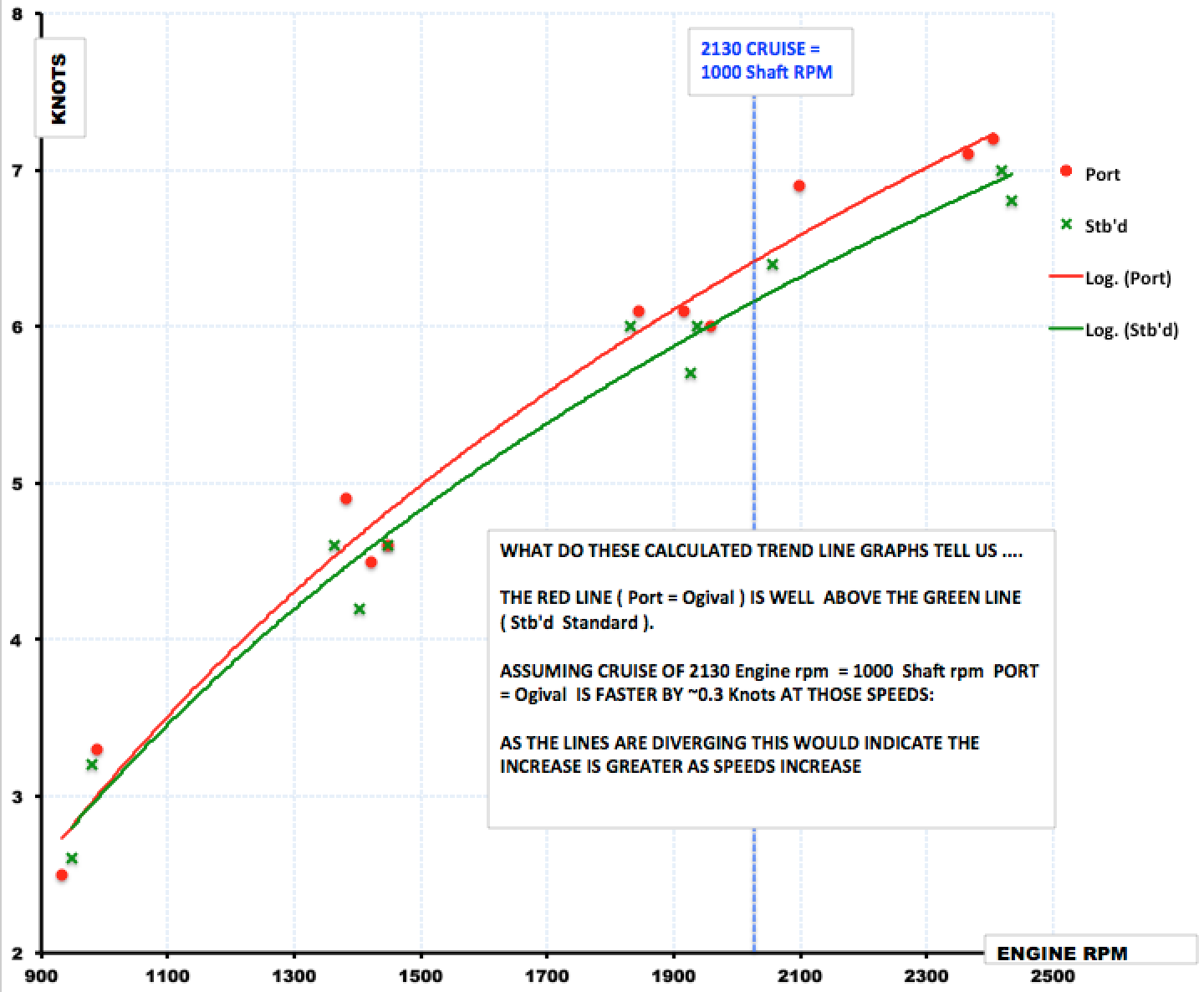
We have been very fortunate to have a customer that fitted an ogival foil set at 18.50" x 22º on one side of his cat and an ordinary foil to the other. A Cat is the ideal test platform as all extraneous variables are netted out - assuming hull loads are similar. The engines were 4JH3's rated 50 hp @ 3800 on 2.13:1 shaft installations. The curves are a logarithim best fit.
AUGUST 2015:
Feedback from another user with an engineering background and good data recording since 2010 with a Yanmar 3YM30 on 2.61:1 has reported after a fortnights motoring on the US Inland waterway that he is achieving an extra 0.3 - 0.5 knots with a new set of ogival modified foils on 16.50" x 22º settings at the same rpm.
DECEMBER 2015:
The performance of the new blade design on a 2004 Catalina 350 cruising the east coast of the United States summer 2015 has now been received. The boat before the installation of the new blade design cruised @ 5.5 kn (on gps ) @ 2400 rpm. Engine is now a Universal M35B rated 35 hp @ 3000 on 2.00 - Blades were 16" nominal x 21º
The tachometer was calibrated with an optical tachometer and adjusted. It would hit 6.6 kn. at WOT (2900 rpm). On flat seas , no head winds and no current.
Bottom was clean for both before and after speed tests Boat was heavy with full fuel ++, water, gear and provisions.
On average I observed the new design provided about .25 kn increase at the high speed range (2200-2500 rpm) over the original design. This observation is based on cruising about 800 miles.
This is no way a “scientific assessment “ as no instrumentation was used to log the data of the performance change but does indicate a change related to the new blade design (only on observations). It also appeared to feather better whilst sailing removing the need to shift into reverse to stop the shaft from free wheeling..
JANUARY 2020:
A cat with 2 x Volvo MD22L's of 50 hp @ 3,000 max on 120S Saildrives with 2.20:1 reduction and 17" x 24º pitch at max reported an approximate increase of ~ 0,5 knots motoring @ 1800 vs previous symetric foils.